 Mobile Menu
Arduino MCP2515 Library
Wikipedia defines the CANBUS as ... a vehicle bus standard designed to allow microcontrollers
and devices to communicate with each other within a vehicle without a host computer. CAN bus is a
message-based protocol, designed specifically for automotive applications but now also used in
other areas such as industrial automation and medical equipment.
I have recently designed some hardware that is based off of the Arduino platform that is used to
interface with my vehicles network. Over the past year, many people have been interested in how
I implemented the CANBUS libraries to the arduino system. Because there weren't too many resources
out at the time to help me out, I figured it would be nice to help out the coding community by providing
my MCP2515 library. Hope this helps!
If you examine the code that I have hosted on GitHub, you will see one of the first methods in the
MCP2515 class is the initCAN method. This is one of the more important methods in the class since
it is going to initialize the controller and help us set the baud rate. The method requires two
parameters, a baud rate, and the slave select pin number.
By allowing the developer to supply the slave select pin, we make this code more portable than some other
solutions that actually have the slave select as a variable or a preprocessor definition. This worked
great for me since in my application I have two different CANBUSes which each operate using a different
slave select. For reference, the Arduino 128 and 328 use the following SPI pins.
One thing that is worth noting about this init method, is that it will leave the controller in CONFIGURATION
mode. You must explicitly set the mode back to NORMAL after you call the init mode unless you have more
configuration to do. The modes of operation are defined in the header file as an enumeration to make it
easier to set a mode.
Setting the baud rate could be complicated if you were to do it manually. A method has been provided called
setBaud to help the developer specify a baud rate for the controller
The baudConst input is an integer based indicator of the baud rate you want to set. If you take a look at the
MCP2515 header file, you will notice a few preprocessor defintions that represent the baud rate.
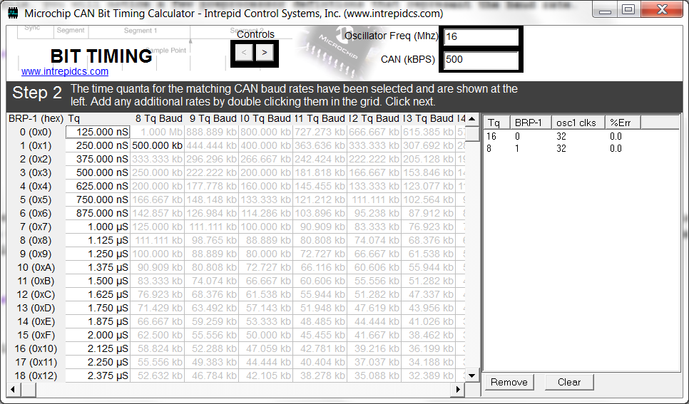
The first part of setting the baud is to calculate the Baud Rate Prescaler (BRP). The easiest way to do this is
to download the CAN Timing Calculator referenced at the top of this page. Once you install the utility, you can
enter the oscillator frequency (in my case, 16Mhz) and the expected baud rate.
Once you enter the information, and click on the right arrow at the top you will be presented with some information
about selecting the BRP and the time quantum. For my case, I pick the TQ of 16, therefore the BRP for a 500K baud
is 0. Follow suit for the rest of the baud rates that you would like to configure in your library.
Arduino CANBUS Library
Refereces
Initializing The Bus
/**
* Initialize the MCP2515 library
* @param	baudConst	The baud rate of the MCP2515 object
* @param	ss			The slave select pin
* @return				True if MCP2515 configured properly
*/
boolean MCP2515::initCAN(const int& baudConst, const int& ss)
SPI Pin
Arduino ATMEGA 128/328
SS/CS
10
MOSI
11
MISO
12
SCK
13
/**
* Enumeration that defines the operation mode for
* the MCP chip
*/
enum CanMode {NORMAL,		 // Normal Mode
		  CONFIGURATION, // Configuration Mode
		  LISTEN};       // Listen only mode
Baud Rate Setting
/**
* Set the CAN Baud Rate
* @param	baudConst	The baud rate to set
* @return				True if baud rate set
*/
boolean MCP2515::setCANBaud(const int& baudConst)
// Data rate selection constants
#define CAN_BAUD_10K 1
#define CAN_BAUD_50K 2
#define CAN_BAUD_100K 3
#define CAN_BAUD_125K 4
#define CAN_BAUD_250K 5
#define CAN_BAUD_500K 6
byte brp;

switch(baudConst)
{
case CAN_BAUD_500K: brp = 0; break;
case CAN_BAUD_250K: brp = 1; break;
case CAN_BAUD_125K: brp = 3; break;
case CAN_BAUD_100K: brp = 4; break;
default: Serial.println("Non-Supported Baud Requested"); return false;
}